


U-TRAK Trackball - White
Ultimarc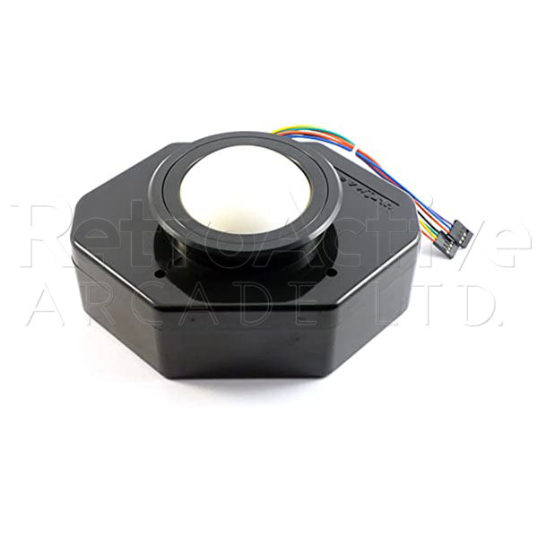


U-Trak Trackball in Cueball White
Ultimarc's U-Trak Trackball has been designed from the ground up to address design flaws, such as mounting to the control panel, that other popular Arcade Trackballs have never sought to improve upon.
The U-Trak Trackball can be mounted directly to your control panel from underneath using the hardware supplied. No mounting plate required which means no router required!
This trackball also has a nice smooth spin right out of the box so you can spend less time breaking in your trackball, and more time enjoying the games you love!
After Installation:
You may find the ball is quite stiff to rotate in certain directions. This is owing to the fact it has to slide over the rollers to some extent and is quite sticky from the manufacturing process. It will ease with use. For an immediate perfect usage, you can apply a small amount of liquid soap or hand cream to the ball.
Includes:
- 1x 3" Solid White U-Trak Trackball & Trim Bezel
Features
Product Features:
- No trackball mount required! This means no routering or recessing!
- Can be mounted with or without optional trim flange
- Panel thickness up to 3/4 inch (19mm)
- Uses specially sourced grease-free bearings. Maximum spin right from new. No bedding-in required.
- 6 Bearing races, 3 stainless-steel shafts for professional durability.
- Optional Full-Speed USB interface (Sold Separately), or connect directly to the I-PAC 2, I-PAC Ultimate I/O, Mini-PAC or Opti-PAC interfaces.
- USB Interface supports left/right mouse buttons.
- 3" Diameter ball.
Mounting Methods
4 Screws and expanding brass inserts are supplied. The inserts are designed to fit into blind holes and nothing shows from the top of the panel. Important note: Check carefully that the supplied screws will not pierce through the top of the panel by checking the length before fitting.
Mounting without trim bezel:
Using a hole saw or fly-cutter, drill a hole 3 1/4 inch diameter (82mm).Note the vertical part of the housing is slightly conical to enable it to be molded in one piece, so to enable a perfect fit you will need to enlarge the hole from the underside of the panel slightly, using a file. Fit the trackball with the arrow on the top of the housing pointing to the rear of the panel. Drill 4 "blind" pilot holes through the mounting holes. Then remove trackball and enlarge holes to 1/4 in (6mm). TIP: To drill blind holes use tape wrapped around drill as a depth guide. Tap the expanding inserts into place. Install trackball and screw into place.
Mounting with trim bezel:
The optimum panel thickness for this method is 5/8 in (17mm). A 3/4 inch panel can be used but the flange will sit 1/8 inch above the ball surround. Using a fly-cutter or hole saw cut a hole approx. 3 3/8 inch (86mm) diameter. You may find a 3 1/2 inch or 90mm hole saw is easier to find and this will work fine. Fit the trackball with the arrow on the top of the housing pointing to the rear of the panel. Drill 4 "blind" pilot holes through the mounting holes. Then remove trackball and enlarge holes to 1/4 in (6mm).Tap the expanding inserts into place. Install trackball and screw into place. Push the bezel over the housing. Glue can be used if required.
Connections
Connection Diagrams:
USB Module to Trackball Control Wiring Diagram
Connecting U-Trak Directly To I-PAC 2
Connections (Non-USB):
| Conn A Red | 5 Volts |
| Conn A Black | GROUND |
| Conn A Purple | X1 |
| Conn A Blue | X2 |
| Conn B Red | 5 Volts |
| Conn B Black | GROUND |
| Conn B Yellow | Y1 |
| Conn B Green | Y2 |
Connections (USB):
The USB interface supports left and right mouse buttons. The wires with contacts push into the two unused locations in the black connector housings. The COM terminals of the mouse button switches should be connected to a convenient ground point (Eg an I-PAC ground, or PC casing).
